Debate rages in the amp builder world about how to do heater wiring, here's my take on the matter.
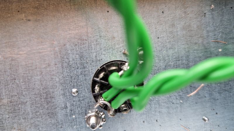
The important thing to achieve is to have the two ends of the AC supply placed so as to avoid creating an electric field that surrounds the grid connections. Every variation I've seen involves laying the heater cables flat against the chassis but this inevitably makes some part of the circuit surround the socket terminals. The solution I settled on was to run the supply standing off the chassis and angled down into the centre of each tube socket. These need a few cables ties as pictured but will keep electric fields as far as possible from the signal electrodes.
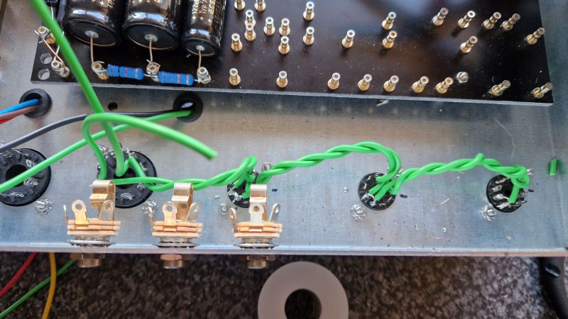
As the 9-pin sockets need to be chained together, a bit of planning goes a long way when attaching the wires. First step is to place (not solder) a wire bridging pins 4 and 5.
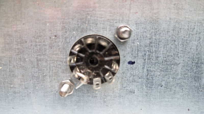
Then add a supply wire to pin 5 and solder that terminal only. Solder two wires into pin 9 to chain the sockets together, add the wire to pin 4 and run this to the next socket in the chain.This avoids trying to thread cable into already-soldered terminal holes and makes for a very neat set of heater wires.